Vecto
VECTOFOX FIELD NOTES
Centerline vs outline tracing: why SVG lines draw twice
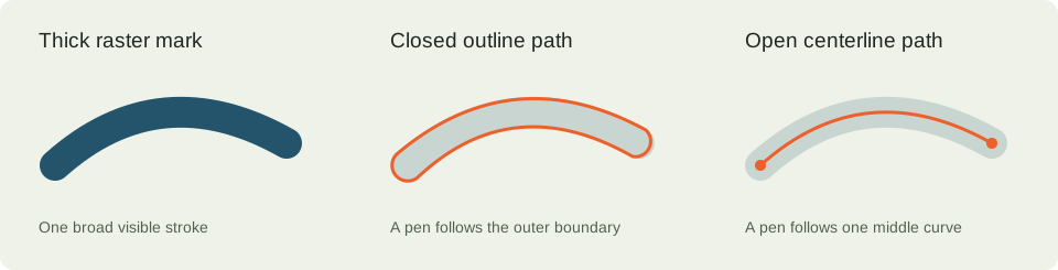
A thick visible mark can be represented as a filled closed contour or as an open path with stroke width. Those are different geometries. A pen following the boundary of the first representation can draw two sides even when there is no duplicated object.
VectoFox documentation · Updated
A closed outline describes the boundary
A filled outline encloses the visible ink region. A broad curved mark has an edge on each side and caps at its ends; one closed path can describe that entire boundary. When displayed with a fill, it looks like a single thick stroke.
A pen or line operation that follows this boundary travels along both edges. That appearance does not by itself prove that the file contains duplicate paths. Changing the fill color in a vector editor does not convert the boundary into a centerline.
A centerline describes a route through the middle
A centerline tracer tries to find a path through the middle of a broad region. An open middle curve with stroke width can visually resemble a filled outline, while directing a pen along one route. Corners, branches and varying stroke widths make this a different reconstruction problem.
LightBurn's documentation describes a separate Center Line Trace option. This is a useful reference for the distinction; it does not mean VectoFox offers the same operation. The VectoFox converter currently writes filled contours and does not provide a centerline or skeleton output.
Check for duplicates as a separate problem
Two identical objects on top of one another can cause a repeated pass along the same route. A single closed outline can instead cause two parallel passes along the two sides of a thick mark. Both may be described as drawing twice, but the repair differs.
Inspect the object list and path geometry in your editor. Work on a copy, separate suspected objects and compare their boundaries. A duplicate-path cleanup will not turn a legitimate closed boundary into a centerline, and replacing the boundary may be wrong when the goal is to cut out a filled shape.
Choose geometry based on the operation
A filled logo for a web page often needs enclosed color regions. A contour cut may need a deliberate outside boundary. A pen plot may need a single open path. The same-looking image does not imply the same correct geometry for all three tasks.
Use software that can generate and inspect the required paths for your particular device. Confirm units, operation type, overlap behavior and the tool's handling of fills. A standard SVG file is not a certification of pen, laser, cutting or embroidery behavior.
- Identify whether the intended output is a fill, outside cut or pen route.
- Inspect whether the file contains closed contours, open paths or duplicates.
- Use a true centerline workflow only when a middle route is actually needed.
- Preview the downstream operation and make an appropriate small test.
Use the line fixture to inspect the actual output
Download the original thin-line image and its balanced SVG. The opaque lines become filled shapes with boundaries; they are not recovered as the original brush movements. The faint alpha=100 line disappears because it falls below the converter's alpha threshold.
This sample is useful for learning how to inspect path geometry before sending a file to a device. It is not a pen-plotter or laser-machine validation, and the schematic above must not be treated as a centerline feature available in the current tool.